BPI:bit板上放置了一个性能强劲的9轴传感器——MPU9250。
- 这里的9轴和空间理解的9轴不一样,其实是相当于分别的3颗3轴传感器(加速度计–Accelerator, 陀螺仪–Gyroscope,磁力计–Magnetometer)的合体。关于这个芯片的详细介绍,大家可以访问github查看文档,连接地址
代码如下
#include "quaternionFilters.h"
#include "MPU9250.h"

#ifdef LCD
#include <Adafruit_GFX.h>
#include <Adafruit_PCD8544.h>

// Using NOKIA 5110 monochrome 84 x 48 pixel display
// pin 9 - Serial clock out (SCLK)
// pin 8 - Serial data out (DIN)
// pin 7 - Data/Command select (D/C)
// pin 5 - LCD chip select (CS)
// pin 6 - LCD reset (RST)
Adafruit_PCD8544 display = Adafruit_PCD8544(9, 8, 7, 5, 6);
#endif // LCD

#define AHRS true        // Set to false for basic data read
#define SerialDebug true // Set to true to get Serial output for debugging

// Pin definitions
int intPin = 12; // These can be changed, 2 and 3 are the Arduinos ext int pins
int myLed = 13;  // Set up pin 13 led for toggling

MPU9250 myIMU;

void setup()
{
  // TWBR = 12;  // 400 kbit/sec I2C speed
  Serial.begin(115200);

  // Set up the interrupt pin, its set as active high, push-pull
  pinMode(intPin, INPUT);
  digitalWrite(intPin, LOW);
  pinMode(myLed, OUTPUT);
  digitalWrite(myLed, HIGH);

#ifdef LCD
  display.begin();         // Ini8ialize the display
  display.setContrast(58); // Set the contrast

  // Start device display with ID of sensor
  display.clearDisplay();
  display.setTextSize(2);
  display.setCursor(0, 0);
  display.print("MPU9250");
  display.setTextSize(1);
  display.setCursor(0, 20);
  display.print("9-DOF 16-bit");
  display.setCursor(0, 30);
  display.print("motion sensor");
  display.setCursor(20, 40);
  display.print("60 ug LSB");
  display.display();
  delay(1000);

  // Set up for data display
  display.setTextSize(1);      // Set text size to normal, 2 is twice normal etc.
  display.setTextColor(BLACK); // Set pixel color; 1 on the monochrome screen
  display.clearDisplay();      // clears the screen and buffer
#endif                         // LCD

  Wire.begin(21, 22, 100000), delay(500);

  // Read the WHO_AM_I register, this is a good test of communication
  byte c = myIMU.readByte(MPU9250_ADDRESS, WHO_AM_I_MPU9250);

  Serial.print("MPU9250 ");
  Serial.print("I AM ");
  Serial.print(c, HEX);
  Serial.print(" I should be ");
  Serial.println(0x71, HEX);

#ifdef LCD
  display.setCursor(20, 0);
  display.print("MPU9250");
  display.setCursor(0, 10);
  display.print("I AM");
  display.setCursor(0, 20);
  display.print(c, HEX);
  display.setCursor(0, 30);
  display.print("I Should Be");
  display.setCursor(0, 40);
  display.print(0x71, HEX);
  display.display();
  delay(1000);
#endif // LCD

  if (c == 0x71) // WHO_AM_I should always be 0x68
  {
    Serial.println("MPU9250 is online...");

    // Start by performing self test and reporting values
    myIMU.MPU9250SelfTest(myIMU.SelfTest);
    Serial.print("x-axis self test: acceleration trim within : ");
    Serial.print(myIMU.SelfTest[0], 1);
    Serial.println("% of factory value");
    Serial.print("y-axis self test: acceleration trim within : ");
    Serial.print(myIMU.SelfTest[1], 1);
    Serial.println("% of factory value");
    Serial.print("z-axis self test: acceleration trim within : ");
    Serial.print(myIMU.SelfTest[2], 1);
    Serial.println("% of factory value");
    Serial.print("x-axis self test: gyration trim within : ");
    Serial.print(myIMU.SelfTest[3], 1);
    Serial.println("% of factory value");
    Serial.print("y-axis self test: gyration trim within : ");
    Serial.print(myIMU.SelfTest[4], 1);
    Serial.println("% of factory value");
    Serial.print("z-axis self test: gyration trim within : ");
    Serial.print(myIMU.SelfTest[5], 1);
    Serial.println("% of factory value");

    // Calibrate gyro and accelerometers, load biases in bias registers
    myIMU.calibrateMPU9250(myIMU.gyroBias, myIMU.accelBias);

#ifdef LCD
    display.clearDisplay();

    display.setCursor(0, 0);
    display.print("MPU9250 bias");
    display.setCursor(0, 8);
    display.print(" x   y   z  ");

    display.setCursor(0, 16);
    display.print((int)(1000 * accelBias[0]));
    display.setCursor(24, 16);
    display.print((int)(1000 * accelBias[1]));
    display.setCursor(48, 16);
    display.print((int)(1000 * accelBias[2]));
    display.setCursor(72, 16);
    display.print("mg");

    display.setCursor(0, 24);
    display.print(myIMU.gyroBias[0], 1);
    display.setCursor(24, 24);
    display.print(myIMU.gyroBias[1], 1);
    display.setCursor(48, 24);
    display.print(myIMU.gyroBias[2], 1);
    display.setCursor(66, 24);
    display.print("o/s");

    display.display();
    delay(1000);
#endif // LCD

    myIMU.initMPU9250();
    // Initialize device for active mode read of acclerometer, gyroscope, and
    // temperature
    Serial.println("MPU9250 initialized for active data mode....");

    // Read the WHO_AM_I register of the magnetometer, this is a good test of
    // communication
    byte d = myIMU.readByte(AK8963_ADDRESS, WHO_AM_I_AK8963);
    Serial.print("AK8963 ");
    Serial.print("I AM ");
    Serial.print(d, HEX);
    Serial.print(" I should be ");
    Serial.println(0x48, HEX);

#ifdef LCD
    display.clearDisplay();
    display.setCursor(20, 0);
    display.print("AK8963");
    display.setCursor(0, 10);
    display.print("I AM");
    display.setCursor(0, 20);
    display.print(d, HEX);
    display.setCursor(0, 30);
    display.print("I Should Be");
    display.setCursor(0, 40);
    display.print(0x48, HEX);
    display.display();
    delay(1000);
#endif // LCD

    // Get magnetometer calibration from AK8963 ROM
    myIMU.initAK8963(myIMU.magCalibration);
    // Initialize device for active mode read of magnetometer
    Serial.println("AK8963 initialized for active data mode....");
    if (SerialDebug)
    {
      //  Serial.println("Calibration values: ");
      Serial.print("X-Axis sensitivity adjustment value ");
      Serial.println(myIMU.magCalibration[0], 2);
      Serial.print("Y-Axis sensitivity adjustment value ");
      Serial.println(myIMU.magCalibration[1], 2);
      Serial.print("Z-Axis sensitivity adjustment value ");
      Serial.println(myIMU.magCalibration[2], 2);
    }

#ifdef LCD
    display.clearDisplay();
    display.setCursor(20, 0);
    display.print("AK8963");
    display.setCursor(0, 10);
    display.print("ASAX ");
    display.setCursor(50, 10);
    display.print(myIMU.magCalibration[0], 2);
    display.setCursor(0, 20);
    display.print("ASAY ");
    display.setCursor(50, 20);
    display.print(myIMU.magCalibration[1], 2);
    display.setCursor(0, 30);
    display.print("ASAZ ");
    display.setCursor(50, 30);
    display.print(myIMU.magCalibration[2], 2);
    display.display();
    delay(1000);
#endif // LCD
  }    // if (c == 0x71)
  else
  {
    Serial.print("Could not connect to MPU9250: 0x");
    Serial.println(c, HEX);
    while (1)
      ; // Loop forever if communication doesn't happen
  }
}

void loop()
{
  // If intPin goes high, all data registers have new data
  // On interrupt, check if data ready interrupt
  if (myIMU.readByte(MPU9250_ADDRESS, INT_STATUS) & 0x01)
  {
    myIMU.readAccelData(myIMU.accelCount); // Read the x/y/z adc values
    myIMU.getAres();

    // Now we'll calculate the accleration value into actual g's
    // This depends on scale being set
    myIMU.ax = (float)myIMU.accelCount[0] * myIMU.aRes; // - accelBias[0];
    myIMU.ay = (float)myIMU.accelCount[1] * myIMU.aRes; // - accelBias[1];
    myIMU.az = (float)myIMU.accelCount[2] * myIMU.aRes; // - accelBias[2];

    myIMU.readGyroData(myIMU.gyroCount); // Read the x/y/z adc values
    myIMU.getGres();

    // Calculate the gyro value into actual degrees per second
    // This depends on scale being set
    myIMU.gx = (float)myIMU.gyroCount[0] * myIMU.gRes;
    myIMU.gy = (float)myIMU.gyroCount[1] * myIMU.gRes;
    myIMU.gz = (float)myIMU.gyroCount[2] * myIMU.gRes;

    myIMU.readMagData(myIMU.magCount); // Read the x/y/z adc values
    myIMU.getMres();
    // User environmental x-axis correction in milliGauss, should be
    // automatically calculated
    myIMU.magbias[0] = +470.;
    // User environmental x-axis correction in milliGauss TODO axis??
    myIMU.magbias[1] = +120.;
    // User environmental x-axis correction in milliGauss
    myIMU.magbias[2] = +125.;

    // Calculate the magnetometer values in milliGauss
    // Include factory calibration per data sheet and user environmental
    // corrections
    // Get actual magnetometer value, this depends on scale being set
    myIMU.mx = (float)myIMU.magCount[0] * myIMU.mRes * myIMU.magCalibration[0] -
               myIMU.magbias[0];
    myIMU.my = (float)myIMU.magCount[1] * myIMU.mRes * myIMU.magCalibration[1] -
               myIMU.magbias[1];
    myIMU.mz = (float)myIMU.magCount[2] * myIMU.mRes * myIMU.magCalibration[2] -
               myIMU.magbias[2];
  } // if (readByte(MPU9250_ADDRESS, INT_STATUS) & 0x01)

  // Must be called before updating quaternions!
  myIMU.updateTime();

  // Sensors x (y)-axis of the accelerometer is aligned with the y (x)-axis of
  // the magnetometer; the magnetometer z-axis (+ down) is opposite to z-axis
  // (+ up) of accelerometer and gyro! We have to make some allowance for this
  // orientationmismatch in feeding the output to the quaternion filter. For the
  // MPU-9250, we have chosen a magnetic rotation that keeps the sensor forward
  // along the x-axis just like in the LSM9DS0 sensor. This rotation can be
  // modified to allow any convenient orientation convention. This is ok by
  // aircraft orientation standards! Pass gyro rate as rad/s
  //  MadgwickQuaternionUpdate(ax, ay, az, gx*PI/180.0f, gy*PI/180.0f, gz*PI/180.0f,  my,  mx, mz);
  MahonyQuaternionUpdate(myIMU.ax, myIMU.ay, myIMU.az, myIMU.gx * DEG_TO_RAD,
                         myIMU.gy * DEG_TO_RAD, myIMU.gz * DEG_TO_RAD, myIMU.my,
                         myIMU.mx, myIMU.mz, myIMU.deltat);

  if (!AHRS)
  {
    myIMU.delt_t = millis() - myIMU.count;
    if (myIMU.delt_t > 500)
    {
      if (SerialDebug)
      {
        // Print acceleration values in milligs!
        Serial.print("X-acceleration: ");
        Serial.print(1000 * myIMU.ax);
        Serial.println(" mg ");
        Serial.print("Y-acceleration: ");
        Serial.print(1000 * myIMU.ay);
        Serial.println(" mg ");
        Serial.print("Z-acceleration: ");
        Serial.print(1000 * myIMU.az);
        Serial.println(" mg ");

        // Print gyro values in degree/sec
        Serial.print("X-gyro rate: ");
        Serial.print(myIMU.gx, 3);
        Serial.println(" degrees/sec ");
        Serial.print("Y-gyro rate: ");
        Serial.print(myIMU.gy, 3);
        Serial.println(" degrees/sec ");
        Serial.print("Z-gyro rate: ");
        Serial.print(myIMU.gz, 3);
        Serial.println(" degrees/sec");

        // Print mag values in degree/sec
        Serial.print("X-mag field: ");
        Serial.print(myIMU.mx);
        Serial.println(" mG ");
        Serial.print("Y-mag field: ");
        Serial.print(myIMU.my);
        Serial.println(" mG ");
        Serial.print("Z-mag field: ");
        Serial.print(myIMU.mz);
        Serial.println(" mG");

        myIMU.tempCount = myIMU.readTempData(); // Read the adc values
        // Temperature in degrees Centigrade
        myIMU.temperature = ((float)myIMU.tempCount) / 333.87 + 21.0;
        // Print temperature in degrees Centigrade
        Serial.print("Temperature is ");
        Serial.print(myIMU.temperature, 1);
        Serial.println(" degrees C");
      }

#ifdef LCD
      display.clearDisplay();
      display.setCursor(0, 0);
      display.print("MPU9250/AK8963");
      display.setCursor(0, 8);
      display.print(" x   y   z  ");

      display.setCursor(0, 16);
      display.print((int)(1000 * myIMU.ax));
      display.setCursor(24, 16);
      display.print((int)(1000 * myIMU.ay));
      display.setCursor(48, 16);
      display.print((int)(1000 * myIMU.az));
      display.setCursor(72, 16);
      display.print("mg");

      display.setCursor(0, 24);
      display.print((int)(myIMU.gx));
      display.setCursor(24, 24);
      display.print((int)(myIMU.gy));
      display.setCursor(48, 24);
      display.print((int)(myIMU.gz));
      display.setCursor(66, 24);
      display.print("o/s");

      display.setCursor(0, 32);
      display.print((int)(myIMU.mx));
      display.setCursor(24, 32);
      display.print((int)(myIMU.my));
      display.setCursor(48, 32);
      display.print((int)(myIMU.mz));
      display.setCursor(72, 32);
      display.print("mG");

      display.setCursor(0, 40);
      display.print("Gyro T ");
      display.setCursor(50, 40);
      display.print(myIMU.temperature, 1);
      display.print(" C");
      display.display();
#endif // LCD

      myIMU.count = millis();
      digitalWrite(myLed, !digitalRead(myLed)); // toggle led
    }                                           // if (myIMU.delt_t > 500)
  }                                             // if (!AHRS)
  else
  {
    // Serial print and/or display at 0.5 s rate independent of data rates
    myIMU.delt_t = millis() - myIMU.count;

    // update LCD once per half-second independent of read rate
    if (myIMU.delt_t > 500)
    {
      if (SerialDebug)
      {
        Serial.print("ax = ");
        Serial.print((int)1000 * myIMU.ax);
        Serial.print(" ay = ");
        Serial.print((int)1000 * myIMU.ay);
        Serial.print(" az = ");
        Serial.print((int)1000 * myIMU.az);
        Serial.println(" mg");

        Serial.print("gx = ");
        Serial.print(myIMU.gx, 2);
        Serial.print(" gy = ");
        Serial.print(myIMU.gy, 2);
        Serial.print(" gz = ");
        Serial.print(myIMU.gz, 2);
        Serial.println(" deg/s");

        Serial.print("mx = ");
        Serial.print((int)myIMU.mx);
        Serial.print(" my = ");
        Serial.print((int)myIMU.my);
        Serial.print(" mz = ");
        Serial.print((int)myIMU.mz);
        Serial.println(" mG");

        Serial.print("q0 = ");
        Serial.print(*getQ());
        Serial.print(" qx = ");
        Serial.print(*(getQ() + 1));
        Serial.print(" qy = ");
        Serial.print(*(getQ() + 2));
        Serial.print(" qz = ");
        Serial.println(*(getQ() + 3));
      }

      // Define output variables from updated quaternion---these are Tait-Bryan
      // angles, commonly used in aircraft orientation. In this coordinate system,
      // the positive z-axis is down toward Earth. Yaw is the angle between Sensor
      // x-axis and Earth magnetic North (or true North if corrected for local
      // declination, looking down on the sensor positive yaw is counterclockwise.
      // Pitch is angle between sensor x-axis and Earth ground plane, toward the
      // Earth is positive, up toward the sky is negative. Roll is angle between
      // sensor y-axis and Earth ground plane, y-axis up is positive roll. These
      // arise from the definition of the homogeneous rotation matrix constructed
      // from quaternions. Tait-Bryan angles as well as Euler angles are
      // non-commutative; that is, the get the correct orientation the rotations
      // must be applied in the correct order which for this configuration is yaw,
      // pitch, and then roll.
      // For more see
      // http://en.wikipedia.org/wiki/Conversion_between_quaternions_and_Euler_angles
      // which has additional links.
      myIMU.yaw = atan2(2.0f * (*(getQ() + 1) * *(getQ() + 2) + *getQ() *
                                                                    *(getQ() + 3)),
                        *getQ() * *getQ() + *(getQ() + 1) * *(getQ() + 1) - *(getQ() + 2) * *(getQ() + 2) - *(getQ() + 3) * *(getQ() + 3));
      myIMU.pitch = -asin(2.0f * (*(getQ() + 1) * *(getQ() + 3) - *getQ() *
                                                                      *(getQ() + 2)));
      myIMU.roll = atan2(2.0f * (*getQ() * *(getQ() + 1) + *(getQ() + 2) *
                                                               *(getQ() + 3)),
                         *getQ() * *getQ() - *(getQ() + 1) * *(getQ() + 1) - *(getQ() + 2) * *(getQ() + 2) + *(getQ() + 3) * *(getQ() + 3));
      myIMU.pitch *= RAD_TO_DEG;
      myIMU.yaw *= RAD_TO_DEG;
      // Declination of SparkFun Electronics (40°05'26.6"N 105°11'05.9"W) is
      // 	8° 30' E  ± 0° 21' (or 8.5°) on 2016-07-19
      // - http://www.ngdc.noaa.gov/geomag-web/#declination
      myIMU.yaw -= 8.5;
      myIMU.roll *= RAD_TO_DEG;

      if (SerialDebug)
      {
        Serial.print("Yaw, Pitch, Roll: ");
        Serial.print(myIMU.yaw, 2);
        Serial.print(", ");
        Serial.print(myIMU.pitch, 2);
        Serial.print(", ");
        Serial.println(myIMU.roll, 2);

        Serial.print("rate = ");
        Serial.print((float)myIMU.sumCount / myIMU.sum, 2);
        Serial.println(" Hz");
      }

#ifdef LCD
      display.clearDisplay();

      display.setCursor(0, 0);
      display.print(" x   y   z  ");

      display.setCursor(0, 8);
      display.print((int)(1000 * myIMU.ax));
      display.setCursor(24, 8);
      display.print((int)(1000 * myIMU.ay));
      display.setCursor(48, 8);
      display.print((int)(1000 * myIMU.az));
      display.setCursor(72, 8);
      display.print("mg");

      display.setCursor(0, 16);
      display.print((int)(myIMU.gx));
      display.setCursor(24, 16);
      display.print((int)(myIMU.gy));
      display.setCursor(48, 16);
      display.print((int)(myIMU.gz));
      display.setCursor(66, 16);
      display.print("o/s");

      display.setCursor(0, 24);
      display.print((int)(myIMU.mx));
      display.setCursor(24, 24);
      display.print((int)(myIMU.my));
      display.setCursor(48, 24);
      display.print((int)(myIMU.mz));
      display.setCursor(72, 24);
      display.print("mG");

      display.setCursor(0, 32);
      display.print((int)(myIMU.yaw));
      display.setCursor(24, 32);
      display.print((int)(myIMU.pitch));
      display.setCursor(48, 32);
      display.print((int)(myIMU.roll));
      display.setCursor(66, 32);
      display.print("ypr");

      // With these settings the filter is updating at a ~145 Hz rate using the
      // Madgwick scheme and >200 Hz using the Mahony scheme even though the
      // display refreshes at only 2 Hz. The filter update rate is determined
      // mostly by the mathematical steps in the respective algorithms, the
      // processor speed (8 MHz for the 3.3V Pro Mini), and the magnetometer ODR:
      // an ODR of 10 Hz for the magnetometer produce the above rates, maximum
      // magnetometer ODR of 100 Hz produces filter update rates of 36 - 145 and
      // ~38 Hz for the Madgwick and Mahony schemes, respectively. This is
      // presumably because the magnetometer read takes longer than the gyro or
      // accelerometer reads. This filter update rate should be fast enough to
      // maintain accurate platform orientation for stabilization control of a
      // fast-moving robot or quadcopter. Compare to the update rate of 200 Hz
      // produced by the on-board Digital Motion Processor of Invensense's MPU6050
      // 6 DoF and MPU9150 9DoF sensors. The 3.3 V 8 MHz Pro Mini is doing pretty
      // well!
      display.setCursor(0, 40);
      display.print("rt: ");
      display.print((float)myIMU.sumCount / myIMU.sum, 2);
      display.print(" Hz");
      display.display();
#endif // LCD

      myIMU.count = millis();
      myIMU.sumCount = 0;
      myIMU.sum = 0;
    } // if (myIMU.delt_t > 500)
  }   // if (AHRS)
}
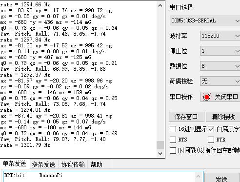
本代码已经上传至github,可以去下载使用github地址
下面是烧录本程序后,串口返回的信息: