@[toc]
目的
利用 ADC(模数转换) 将真实世界的模拟信号,例如温度、压力、声音或者图像等,需要转换成更容易储存、处理和发射的数字形式。利用 DAC(数模转换) 数字信号转换为模拟信号,从而使得它们能够被外界(人或其他非数字系统)识别。
DAC
基础使用
下列是 DAC 基础使用代码,将代码烧入模块中,实现将数字信号转换为模拟信号。
#include "Arduino.h"

void setup()
{
    dacWrite(20, 100); //IO20 DAC输出 100*3.3V/255≈1.294V
}
主要函数
-
void dacWrite(uint8_t pin, uint8_t value)
在对应的引脚输出电压
示例代码
略^ ^
ADC
基础使用
下列是 ADC 基础使用代码,将代码烧入模块中,实现将模拟信号转换为数字信号。
#include "Arduino.h"

void setup()
{
    Serial.begin(115200);
    Serial.println();

    float vtmp = analogRead(34); //从IO34 利用 ADC 获取电压
    printf("%.3f",vtmp);
}

void loop()
{

}
主要函数
========= 以下为阻塞采样 =========
-
uint16_t analogRead(uint8_t pin)
获取指定IO口的模拟电压数据(该方法将阻塞直到采集完成) -
void analogReadResolution(uint8_t bits)
设置模拟数据读取分辨率,取值1~16,默认为12。如果介于9和12之间,它将等于设置的硬件分辨率,否则值将被移动 -
void analogSetWidth(uint8_t bits)
设置ADC采样分辨率,取值9~12,默认为12 -
void analogSetCycles(uint8_t cycles)
设置单次采样的周期,取值1~255,默认为8 -
void analogSetSamples(uint8_t samples)
设置单次采样的实际采样次数,取值1~255,默认为1;
该项的设置相当于提高了ADC的灵敏度,比如该值为2,则采样获得数据就是真实数据的2倍 -
void analogSetClockDiv(uint8_t clockDiv)
设置ADC时钟分频系数,取值1~255,默认为1 -
void analogSetAttenuation(adc_attenuation_t attenuation)
设置ADC全局输入衰减,取值ADC_0db, ADC_2_5db, ADC_6db, ADC_11db,默认为11db
当 VDD_A 为 3.3V 时:
| 条件 | 最大量程 |
|---|---|
| 0dB | 1.1V |
| 2.5dB | 1.5V |
| 6dB | 2.2V |
| 11dB | 3.9V(最大可以采集到3.3V电压) |
-
void analogSetPinAttenuation(uint8_t pin, adc_attenuation_t attenuation)
设置单独某个IO口的输入衰减
========= 以下为非阻塞采样 =========
-
bool adcAttachPin(uint8_t pin)
将引脚连接到 ADC(还将清除可能打开的任何其他模拟模式) -
bool adcStart(uint8_t pin)
在连接的引脚上启动 ADC 转换 -
bool adcBusy(uint8_t pin)
检查 ADC 转换是否在进行 -
uint16_t adcEnd(uint8_t pin)
获取转换结果(如果尚未完成将等待)
示例代码
阻塞采样
#include "Arduino.h"
#include "math.h"

const float R1 = 10000.0; //10K
const float T2 = (273.15 + 25.0);
const float Bx = 3950.0;    // B值
const float Ka = 273.15;

void setup()
{

  Serial.begin(115200);
  Serial.println();
}

int tempCount(float vtmp)       // 温度转换
{
  float Rt;
  float temp;
  float v0 = (vtmp * 3.9) / 4095.0;

  Rt=(3.3-v0)/v0*R1;
  temp = Rt/R1 ;
  temp = log10(temp);
  temp /= Bx;
  temp += (1 / T2);
  temp = 1 / (temp);
  temp -= Ka;
  return temp;
}

void loop()
{
  float vtmp = analogRead(34); //IO34 ADC获取电压
  float temp = tempCount(vtmp);

  Serial.printf("T:%f\n", temp);
  Serial.println();
  Serial.printf("C:%f\n", vtmp);
  Serial.println();
  Serial.printf("V:%.3fV\n", vtmp * 3.9 / 4095);
  Serial.println();

  delay(1000);
}
非阻塞采样
#include "Arduino.h"
#include "math.h"
const float R1 = 10000.0; //10K
const float T2 = (273.15 + 25.0);
const float Bx = 3950.0; // B值
const float Ka = 273.15;
void setup()
{
Serial.begin(115200);
while (adcAttachPin(34) != 1)
{
}
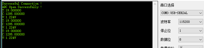
Serial.printf("Successful Connection !");
Serial.println();
while (adcStart(34) != 1)
{
}
Serial.printf("ADC Open Successfully !");
Serial.println();
}
int tempCount(float vtmp) // 温度转换
{
float Rt;
float temp;
float v0 = (vtmp * 3.9) / 4095.0;
Rt = (3.3 - v0) / v0 * R1;
temp = Rt / R1;
temp = log10(temp);
temp /= Bx;
temp += (1 / T2);
temp = 1 / (temp);
temp -= Ka;
return temp;
}
void loop()
{
float vtmp; // ADC获取电压
float temp;
if (adcBusy(34) == 0)
{
vtmp = adcEnd(34);
temp = tempCount(vtmp);
Serial.printf("T:%f\n", temp);
Serial.println();
Serial.printf("C:%f\n", vtmp);
Serial.println();
Serial.printf("V:%.3fV\n", vtmp * 3.9 / 4095);
Serial.println();
delay(1000);
}
}
现象
阻塞采样 与 非阻塞采样 的测试结果差不多,区别就是在非阻塞采样会检测是否连接成功
总结
ADC 和 DAC 在 Arduino 中实现起来并不难。DAC 主要函数只有 void dacWrite(uint8_t pin, uint8_t value) 在 ADC 中,函数较多,而且有阻塞采样和非阻塞采样两个方式。